Product inspection systems, such as Automated Optical Inspection (AOI) solutions, are frequently used in manufacturing to detect product defects and improve quality. At the same time, some manufacturers complain about cases of false detection, which undermines the effectiveness of AOI systems.
In the case study below, we tell how Intelliarts reduced false calls in the partner’s AOI solution. By using a machine learning approach, we helped a printed circuit board (PCB) producer to increase the efficiency of their AOI system and, hence, solve the problem of downtime and massive maintenance costs.
Company overview
Our customer (under NDA) is a world leader in producing PCBs, schemes, and chips for companies from different industries, including the automotive industry, consumer electronics, industrial manufacturing, home safety, and security. The manufacturer is strictly focused on producing innovative, top-quality products and solutions for its end-users.
Read also: Digital Twin: A New Tool in Manufacturers’ Arsenal
Since quality matters a lot for this PCB and IC producer, our customer places high value on product inspection. Defect detection is its major strength, which the company enforces aiming at producing best-in-class products with no effect on production. The leadership understands well that without quality product inspection, defects in their products risk increasing costs and a massive waste of resources, along with shortening the useful life of manufactured goods.
The company chooses automatic product defect detection over manual detection as it obviously works better for product inspection. For one thing, it guarantees more precision and speed; for another, it adapts better to new environments.
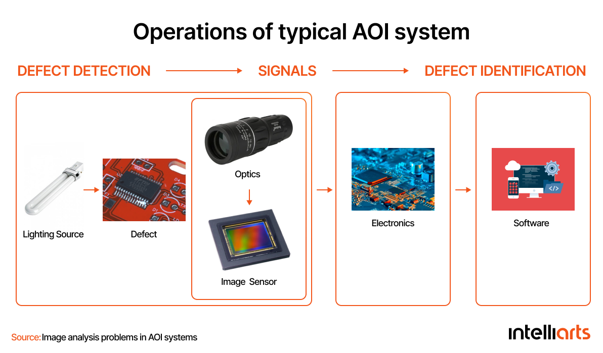
Like many others in the industry, the manufacturer we partnered with relies on the use of Automated Optical Inspection (AOI). The idea of AOI is to automatically look and test for defects in PCB and IC assembly lines. A typical AOI system (similar to the one used by our customer) consists of a lighting source, optical sensors (i.e., cameras), an image processor (i.e., computer), and its software (figure 1).
So, the product inspection system receives a digital image of the object illuminated by the lighting source and transfers it further to the computer for analysis. The software then makes a reliable pass/fail decision based on the features extracted from the acquired images and classifying them into defective and non-defective.
Manual product inspection goes into the manufacturer’s pipeline we worked with. The station operator comes and rechecks the product every time the system detects the defect. A long time ago, the AOI system was introduced to manufacturing to reduce the amount of manual work and unburden AOI inspectors. Still, the manufacturer cannot do without human expertise, believing it’s contributing to its performance.
Business challenge
Unfortunately, based on the work of our customer, we can see that no automated optical inspection system is ideal for 100% when it comes to defect detection. The customer reached out to Intelliarts with the false detection of polarity issues made by the AOI system. This problem caused downtime and put an extra toll on the manufacturer’s productivity. On its factory floor, the procedure is as follows: each production defect reported by the automated optical inspection system has to be verified. The company stops the manufacturing of the particular PCB or chip entirely for an unspecified amount of time.
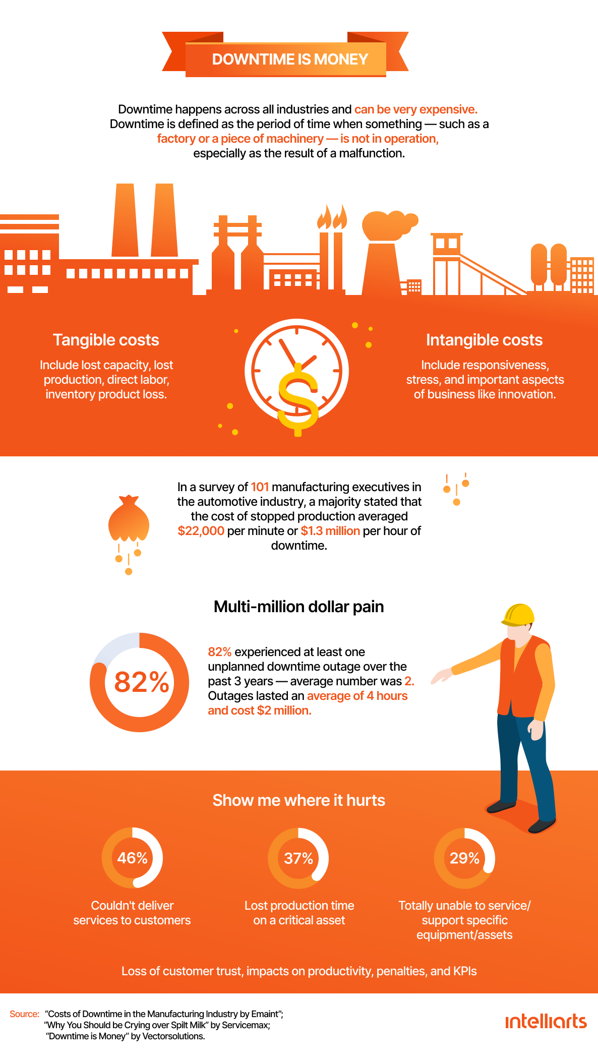
No doubt false calls are costly in manufacturing. If the machine reports a product defect that turns out to be false detection, then its verification creates no real value and generates extra costs. These costs extend but are not limited to labor, maintenance, capital equipment, and others. The case study by Orbotech has calculated the approximate cost of false detection for PCB reported by AOIs, and it’s almost $7000 per panel annually. The model they created is linear, which means for two extra false calls per panel, this sum doubles, and so on.
The highest cost, though, is caused by industrial downtime. According to the Vanson Bourne Research Study, almost 82% of manufacturers that have faced unplanned downtime in the last three years experienced two outages of an average of four hours, which estimatedly equaled $2 million. Moreover, the higher the percentage of false defects, the higher the chance that an AOI operator will miss a real defect the next time due to negligence or inattentiveness. Together, all this explains why reaching zero downtime should be as important for manufacturers as improving quality and optimizing productivity.
Read the Predictive Maintenance White Paper to discover how to improve uptime and cut your maintenance costs in the manufacturing industry.
The manufacturer we worked with could boast of the 95% effectiveness of its automated optical inspection system, which is a great indicator. The machine failed rarely. But as we understood during the data exploration stage, when it did happen, it caused lots of trouble for the customer (which was the reason they contacted us in the first place).
As said, the problem was caused by the false detection of polarity components. Polarity refers to the state when the positive and negative poles or the first pin of the component remain in the same direction as the positive and negative poles or the first pin on the PCB or IC. If the direction of the component and the PCB or IC board doesn’t match, it’s known as the reverse defect. Below is an example of the positive marking of the PCB and its components in tantalum capacitors. Some markings we see in the image include color band marking; “+” marking; and diagonal one.

The danger for the customer’s production line was related to the batch accidents that could happen because of the wrong orientation of the polarity components. This could then lead to the failure of the whole PCB or IC assembly line. So, the manufacturer couldn’t ignore the reported defects. Nonetheless, whenever the AOI system reported the polarity issue, the production process stopped, causing idle time on the production line. This was the main challenge Intelliarts had to solve.
Solution
While collaborating with the customer, we have offered the manufacturer to build a machine learning (ML) model whose task will be to double-check if the polarity is actually missing. In this way, the customer could reduce the number of false detections during product inspection and the time spent on manual work of the AOI operator. The model was planned to be as fast as possible (less than one second for inference) so the model wouldn’t add to the overhead costs while the manufacturer would no longer lose its productivity.
Data ingestion and analysis
As usual, our Intelliarts team has started the work on the project from data ingestion and analysis, which aimed at transferring the customer’s data from one source to another for further processing and analysis. The customer provided us with a dataset of images depicting the polarity check issue spotted by the AOI system. We’ve analyzed this customer’s data, purposing to make sense of it, get some patterns, and test hypotheses based on the provided dataset.
Not to go into detail, the data exploratory analysis made us understand that the manufacturer had a limited amount of images with polarity check problems. Out of those images we’ve got for analysis, only 164 images proved to be false positive, i.e., they depicted the false polarity check issue detected by the automated optical inspection system.
Based on this analysis, we also found meta information that contained the coordinates of where the polarity marking should have been. According to this info, we could check whether the polarity issue was indeed present or falsely detected. To explain it further, the polarity issue differs from one chip to another. The idea is as follows: there is a PCB or IC, and it should stand in the “correct” polarity position, i.e., correctly placed horizontally and vertically.
After the exploratory analysis, the Intelliarts team discovered that to solve this problem, there should be a so-called polarity marking placed in certain coordinates. This should help to check whether or not the defect was real. The task of the algorithm was the next one: there was a circuit, and the model had to check the placement of the polarity marking. If it was present in the right coordinates, the circuit or board was placed correctly. If the marking was absent (not in the right coordinates), then the board was placed incorrectly, and there was a polarity defect.
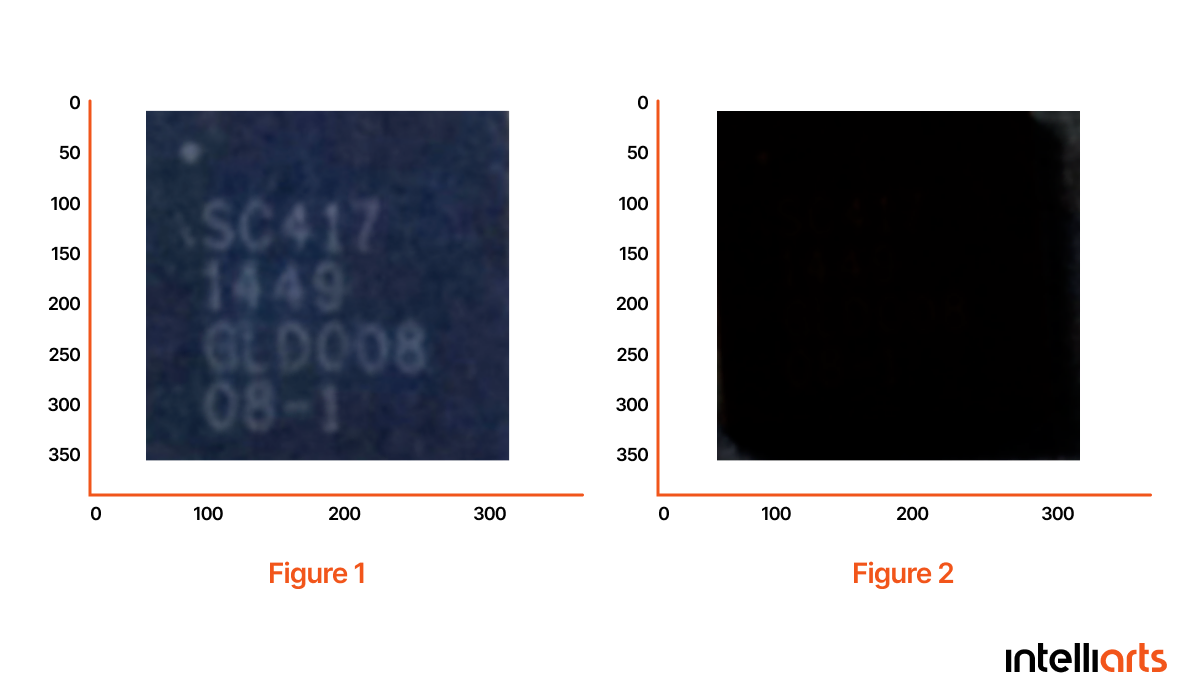
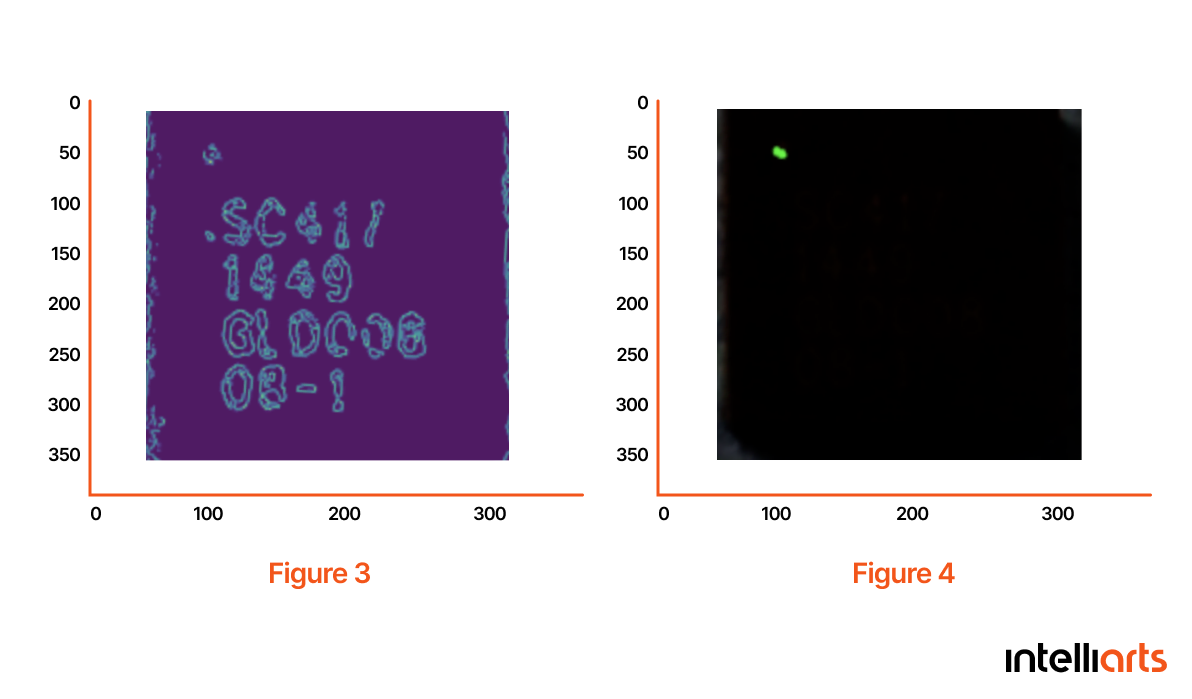
Now a brief background story of how the prototype was built. Generally, we applied a classical computer vision approach using the OpenCV library. We took a random picture of a chip (Fig. 1) and tried to detect the white marking that represented polarity. At first, we experimented with different degrees of darkening the image. Fig. 2 exemplifies the highest degree of darkening that our algorithm had worked with. Then, we applied an edge detection algorithm to find essential edges. Fig. 3 shows the results we’ve got. Finally, we’ve applied the algorithm to find the coordinates of edges in the desired area. You can see the obtained results in Fig. 4.
We’ve tested this approach using a bunch of images provided by the manufacturer. The results looked promising to us, so we planned to create an OpenCV-based prototype during the Proof Of Concept implementation.
Read another insightful case study on the use of the computer vision approach.
Model development
Together with the customer, we have moved to the model development phase now. With the current approach, we were lucky enough to achieve 99% accuracy in the machine learning model. However, as said, a small amount of data (164 images) was collected, which isn’t enough to test the algorithm properly. We recommended the manufacturer to collect more data by adding it synthetically and making sure the algorithm would work the same effectively.
If we follow this scenario, we’ll then try to use neural networks. Unlike traditional machine learning techniques, neural network structures learn and can make reliable decisions on their own. In contrast, machine learning-based models make decisions based on what they have learned from the data only.

During this phase, the Intelliarts team is going to:
-
Build an ML model based on classical computer vision algorithms, for example, by using the OpenCV library or convolutional neural networks
-
Test the model using already collected data for two years
-
Verify the model results on an independent dataset
Model integration
Since this is a full-cycle ML project, we’re also going to provide the company with effective model integration into their process of product inspection and the AOI system, in particular. This step requires the Intelliarts team to think about modeling “in large”. For example, we’ll have to establish at what phase of the product inspection the ML model will provide the best results in checking the polarity issue, how to integrate the model into the existing system the most smoothly, and how to manage it.
To get more specific, the integration phase will include:
-
Deploying the model to the local computer connected to the AOI system
-
Implementing a code-based system to pool data from MS SQL when the new records arrive and send it to the ML inference
-
Implementing a code-based system that integrates model results into the existing system by writing to database updated results
Business value
As said, we’re progressing with the model development, building the synthetic data for the customer in order to get more data for testing the algorithms and, thus, increasing the accuracy of the results. Our machine learning-powered solution for false detected polarity checks is already showing 99% accuracy. But we’d like to make sure it stays the same efficient with more data.
Read also: Machine Failure Prediction using Machine learning [Case Study]
At the end of this project, the PCB and IC manufacturer will benefit from:
-
Getting an effective ML model for polarity checks detected by the customer’s AOI system
-
The ML model with over 90% accuracy and fully integrated with the existing AOI system
-
An ability to reduce the number of false calls, which cause lengthy delays in its production and costly downtimes
-
Significant labor costs savings since the ML-powered solution will process false detected polarity issues automatically, and the user, i.e. the station operator will be less involved in product inspection
-
Uptime improvements since the ML-powered solution will be able to prevent repeated downtimes in production caused by the need to check the detected polarity issue manually
-
Increase in quality products — the more false detections happen, the more you risk to overlook the real defect. The AOI operators have to check more chips in this case and may become tired and less attentive. In contrast, the ML solution will get the manufacturer fewer false detections and, hence, more quality products
-
Special training or a set of recommendations to help the personnel of the company get used to the ML-powered solution, understand its benefits, and how to use it in the most efficient way
Wrap up
Implementing predictive maintenance for manufacturing through machine learning can significantly enhance the reliability and efficiency of industrial equipment. As evident, machine learning can be a useful tool to deal with the false calls detected by AOI systems. Aside from cutting maintenance costs and reducing idle time on the production line, manufacturers can also improve the product inspection process and, thus, the quality of their products.
Developing an ML-powered solution, deploying, and integrating it into the existing system can yet be challenging. The company has to prepare and preprocess the dataset, supplement it if needed, and analyze it effectively to get valuable business insights. For instance, in AI car damage detection, high-quality image datasets are essential for training models to accurately assess vehicle damage. It can use these insights to strengthen the ML solution later. Then, the data science team can move to the choice of the model, training, fine-tuning the parameters, model evaluation, and monitoring. As a full-cycle project, ML model integration can also take place. This is truly valuable since the manufacturer can start its use the very next day.
Our manufacturing software developers have wide domain knowledge and experience in working on full-cycle manufacturing projects. This allows us to create ML solutions that meet manufacturers’ business needs. So, feel free to reach out to us to solve the challenge of false detection alarms or any similar issues related to product inspection and equipment failures.


